DIY Home Improvement Forum banner

Errant Septic Pump Wiring Troubleshoot

8.5K views 41 replies 9 participants last post by  Mark*57Shark  
#1 ·
Howdy -
I just finished overhauling the wiring to an in-tank septic pump.


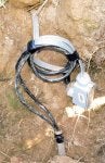
I had to remove a buried extension cord pigtailed to proper underground-rated romex, the underground romex is now mated with my new underground rated pigtail; I used a kit that connected them with a screw-secured metal "junction block", and that was covered by a heat-shrink tube rated for direct burial.


At the terminal of the feed to the pump, I wired the hot feed through a 2-wire float switch that operates the pump, and connected my hot neutral and ground wires to the romex, then I put those wire-nutted connections inside a watertight box, and siliconed the holes to prevent water from intruding. Prior to hooking all that up, I tested the float switch and the pump, both individually and then in tandem, and they worked fine as expected when I powered them by an extension cord wired temporarily into their combined circuit.


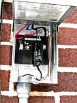
I had the local electric company drop the line to the house and remove the face of the meter, so I could wire my new circuit panel feeding the pump circuit. I connected my black hot feed to the left bottom leg, the neutral feed to the right bottom leg, and the ground to the center ground leg. All these connections run under a 1/2" bolt-secured metal clamp in the main meter box, the same lugs that the main house feed wires attach to. When I looked at the existing wiring running to the same lugs I connected to, they had a black wire on the left lug, and a red wire to the right lug, and the (what I thought was) ground wire connected to the center ground lug - these wires exit through the right side of the meter box and feed power to the remote shed.


I have 124V between the hot and ground, and 124V between the neutral and ground, but I have 0 Volts between my hot and neutral connections, all readings taken from inside my new circuit panel. FYI - my new panel feed wires should be Black to hot, Blue to neutral, and Red to ground, coming in from the top of the new box, fed through the bottom of the main meter box. The buried romex is powered by Black to hot, White to neutral, bare wire to ground, all connected inside the new circuit box.


The pump did nothing when power was activated by closing the new breaker. Everything in the house and shed works the same as before.


Did I botch the wiring connecting my new circuit panel to the main meter box? Or (hopefully - easier/less hassle and wait to fix), did I botch my connections out at the pump well? I am guessing perhaps I have my neutral and ground connections incorrectly attached to the main feed. I have searched online for a proper description of how to make those 3 connections inside the main meter box, but I could not find a diagram.

THANK YOU for your advice and input!!
-Mark
 

Attachments

#2 ·
Did you measure the output of the circuit breaker? If you are getting 0 volts then move the circuit breaker. With only one hot feeding the panel half the slots are not going to have power. I can't tell from the picture if you are using a good one or not.
Or you could move the panel hot feed to the other lug so the breaker can stay where it is not have to punch another slot out from the panel face.
 
#3 ·
Thanks for your reply!


The Black hot feed comes down through the top of the new circuit box, and connects to a large screw lug at the upper right of the circuit breaker, the other available large screw lug is on the unused left slot to the left of the breaker I installed. I used that slot on the right side because that slot was already knocked-out in the (uninstalled in picture) front cover plate, and I didn't want to open the left one and leave an unused slot open in the front plate.


With the breaker OFF, I get 119V between lower breaker output wire and the neutral buss, and around 2.54V and slowly leaking down, between breaker output and ground - and still 123V between neutral and ground.

Thank You!
-Mark
 
#7 ·
Well, seems it's energizing the ground :surprise:

OP, You need to shut this down, and learn how to do a 240V connection.
From your description, you wired one leg of the hot to ground (which is why your not seeing a potential to ground.)

My guess is that the RED wire is HOT . Be careful when you move it to the other lug on your sub panel.
 
#8 ·
I connected my black hot feed to the left bottom leg, the neutral feed to the right bottom leg, and the ground to the center ground leg. All these connections run under a 1/2" bolt-secured metal clamp in the main meter box, the same lugs that the main house feed wires attach to. When I looked at the existing wiring running to the same lugs I connected to, they had a black wire on the left lug, and a red wire to the right lug, and the (what I thought was) ground wire connected to the center ground lug - these wires exit through the right side of the meter box and feed power to the remote shed.

The left and right lugs in the meter box are both hot. The center lug is the neutral, which gets bonded to ground.


So I'm thinking you have 240V wired to your pump through a single pole breaker. Is the pump a 120V or 240V pump?


Does the meter have dual lugs? Or did you place both the wires for your main panel and the new pump panel under one set of lugs?


Do you have any photos of how you wired things in the meter box before closing it back up?
 
#10 ·
Thank You! The local little hardware store had no green for ground, or white for neutral, in that wire gauge - so I opted for the chromatic opposite of green (which is red) for my ground, and I used blue for neutral in place of white (super-white laundry uses "bluing", I remember from my long-deceased Grandmother)-- SORRY for my Polack color scheme!! Had to use what I could get... Maybe I better tag them for future techs' ID... PLEASE ACCEPT MY HUMBLE APOLOGIES FOR BEING A DUMMY!!
 
#11 ·
SORRY for my absence - been in bed all day with a 24-hour bug... Just taking the pics this morning had me wiped out all day...

Just now got up to eat & then upchucked my banana - whew, feeling a little better but also a little bewildered now. ENJOY your youth and health while you have it - rof, lol.


THANKS for all the respondents!!!
Will give this another shot in the morning when I feel better,

I seem to be on the mend now.
 
#12 ·
Sorry, I was too dumb to think to take pics of my botched install.
I could cut the little wire lock thingy the electric Co. guy put back on there,
and I think I could remove that meter face CAREFULLY as I watched him do twice now.


The setup looks vaguely like a 5-spot on a dice - two lugs on top, one in the middle, and two on the bottom. The wire from the pole (if I remember correctly) hooks to the top two, and its thick braided metal shield hooks up to the middle, then the (I presume they are the) big thick wires feeding the house interior panel hook up to the bottom two lugs as well as a (I presume it's a) ground the center one.
 
#14 ·
Please feel free to FLAME ME for my stupidity -
just trying to save my absentee owner Son from paying large for a proper electrician,
it SEEMED like an easy basic job until I couldn't locate any meter box legend online DOH!!


I do have some experience remodeling and rewiring a home bathroom, and some minor repair work on guitars and amps. JUST ENOUGH KNOWLEDGE TO BE DANGEROUS - THANKS FOR BEING HERE FOR ME, GUYS!!!
 
#15 ·
THANK YOU!! I WILL DO AS YOU SAY AND NOT MONKEY WITH IT!
Besides, when the guy came out a month ago for a different disconnect, he saw I had removed the lock-tag for a simple no-touch look-see, and told me that was a BIG NO-NO. I do realise I could join The Honeymooners' Alice Kramden up on the Moon if I get zapped... Will wait for the company to get my cutoff scheduled, hoping to get proper definition here by then - Thank You!
 
#17 ·
While you are awaiting your utility to schedule another cut-off you probably have a problem. It certainly sounds like you have connected the circuit across 240v. Assuming that your septic pump is 120v, you may have fried it unless it has some kind of repairable internal protection, so your septic system won't work and once the pump chamber is full it will probably back up into the house.
The black leg is protected by the breaker (hopefully 'off' until this gets sorted out) but the blue leg remains hot and unprotected from all of the current that your utility has to offer.
 
#19 ·
I feel pretty stupid, now that I recall how all the connections are made inside my main circuit panel. I believe I should have put both the neutral and the ground wires together at the ground attachment - the center lug - under the electric meter? The power company is coming out today for another temporary disconnect, I will ask the electric man at that time. THANK YOU for your help and input!!
 
#22 ·
- END OF THREAD, PLEASE CLOSE -

Well, as they say, God protects drunks and fools...
What ignorant wiring should have resulted in a fried pump, was disallowed from damaging it by my ignorant wiring at the terminal end. Upon cramming my connections into the smaller of two waterproof boxes I bought, I inadvertently pulled-loose the neutral connection, effectively rendering the circuit open. I asked the electric man to confirm my guess that the neutral and ground connections at the main meter box should be attached to the same ground lug, and he concurred. When I pulled the pump out of the well to check its condition, and then opened my watertight junction, I discovered what looked like might have been a neutral wire pulled loose from its slippery connection under a wire nut, to its hard straight solid copper feed. I reattached the neutral and everything works fine - fried pump was averted by my own amateurish ignorance - and God's help. Murphy's Law be damned this time!!

I will use the larger box so everything is not crammed together inside it.


THANKS TO ALL who delivered valuable experienced input to my thread!


- END OF THREAD, PLEASE CLOSE -
 
#24 ·
- END OF THREAD, PLEASE CLOSE -
Well, as they say, God protects drunks and fools...
Maybe that's why God had me watching this thread.
Trust me, you still need protecting !


I asked the electric man to confirm my guess that the neutral and ground connections at the main meter box should be attached to the same ground lug, and he concurred.
There should be a bonding screw in that panel. You need to make sure it is in fact there . Not sure if that's what the 'electric man' did.

When I pulled the pump out of the well to check its condition, and then opened my watertight junction, I discovered what looked like might have been a neutral wire pulled loose from its slippery connection under a wire nut, to its hard straight solid copper feed. I reattached the neutral and everything works fine - fried pump was averted by my own amateurish ignorance - and God's help. Murphy's Law be damned this time!!
Since you didn't fry the pump, I'll assume that it is a 240V pump.

Unless the 'electric man' moved the 'blue' hot conductor from the neutral bar, the next person to add something to that panel will have a phase to phase short.

If it is in fact a 240V motor, it should be fed with a 2 pole breaker.
As it is now (from what I have gathered), You have no way of shutting one of the poles off in case of maintenance on the motor.
 
#27 ·
You have so many code violations.
You can not have 2 wires under one lug.
You can bond the neutral and ground inside the panel.
A utility lineman is not an electrician, and they follow different rules.

You should have found a way to come out of the main panel to feed the pump.